I was really doubting if my title really fits t my blog. Help me guys think about my title. You can post your suggestions.
These blogs include some ideas and information about circuit analysis and three phase circuits. You may write your comments and suggestions so I can go deeper and you can have much informative ideas.
Tuesday, 3 April 2012
Friday, 30 March 2012
Three - Phase Circuits
He who cannot forgive others breaks the bridge over which he must pass himself.
-G. Herbert
Three-Phase AC Circuits
A single-phase (1- ) AC that is transmitted through a transmission line (consisting of a pair of wires) to a load, attention now turns to a three-phase (3- ) AC power system, in which three AC sources operate at the same frequency but with different phases. A 3- AC power system has the following advantages over a 1- AC power system:
1. The horsepower rating of three-phase motors and the KVA (kilo-voltamp) rating of three-phase transformers is about 150% greater than for single-phase motors or transformers with a similar frame size.
2. The power delivered by a single-phase system pulsates, Figure 12-1.The power falls to zero three times during each cycle. The power delivered by a three-phase circuit pulsates also, but it never falls to
zero, Figure 12-2. In a three-phase system, the power delivered to the load is the same at any instant. This produces superior operating characteristics for three-phase motors.
3. In a balanced three-phase system, the conductors need be only about 75% the size of conductors for a single-phase two-wire system of the same KVA rating. This helps offset the cost of supplying the third
conductor required by three-phase systems.
Balanced Three Phase Circuits
Single phase power has a sine wave voltage that crosses zero before reversing its polarity. In the region near the zero-crossing there is not much power. At zero there is none at all. So single phase loads often need some trickery to deliver output in this area. Often it is just the inertia of the motor or appliance.
Three phase power is always delivering power on one of its phases, and is thus preferred for generators, motors, machines and appliances that use lots of power.
If the application is large power, or small power with weight restrictions (like automobiles!) Three Phase is preferred. DC (Direct Current) is the next step up for smooth high-power devices but requires rectification, regulation and smoothing to be useful.
Another problem with DC is that, for efficient long distance transmission, it cannot be simply converted to much higher voltages than the voltage at which it was generated at the power station. Similarly DC cannot be transformed down to safer, much lower mains voltages for use by consumers.
AC (Alternating Current) is used for high power generation and distribution because it can easily be transformed, using transformers, to achieve very efficient power transmission over very long distances and can then be transformed down to low voltages for distribution to consumers.
Two phase, and higher multi-phases are also used but very rarely.
Wye to wye connection
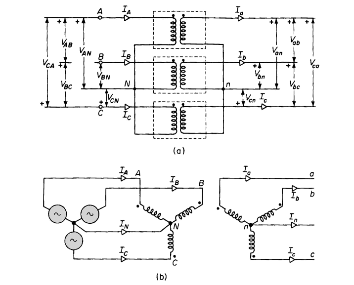
Three single-phase transformers with their primaries and secondaries both connected in wye are shown in Figs. 6-23(a) and 6-23(b). The primary neutral is shown connected to the neutral of the source and the secondary neutral connected to that coming from the load. In many applications the neutral connection consists of ground. Connecting the primary neutral to the neutral of source assures balanced line-to-neutral voltage even if the load is unbalanced or if the transformers have unequal exciting admittances. The equivalent circuits of Fig. 6-11, 6-13, and 6-14 apply to each of the three transformers connected wye-wye with or without the ideal transformer just as they do in the delta-delta arrangement. Here also, if the transformers are identical and supply balanced 3-phase load, each transformer carries one-third of the 3-phase load.
It can be seen from Fig. 6-23 that the current in the transformer winding is the line current in the wye connection. The secondary currents Ia, Ib, and Ic are therefore practically in phase with the primary currents IA, IB, and IC and if the exciting current is neglected, the current ratios are the reciprocals of the turns ratio, i.e.
[6-89] |
Also, if the leakage impedance is neglected, the voltage ratios equal the turns ratios, thus
[6-90] |
Phasor diagrams are shown for the wye-wye arrangement in Fig. 6-24. The wye connection is generally used in high-voltage applications because
Wye-Delta Connection
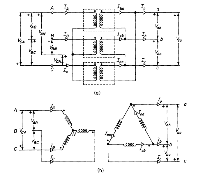
The wye-delta connection affords the advantage of the wye-wye connection without the resulting disadvantage of unbalanced voltages and third harmonics in the line-to-neutral voltages when operating without the neutral wire. The wye-delta arrangement is shown in Fig. 6-25. In high-voltage transmission systems, the high side of a transformer bank or of a 3-phase transformer is generally connected in wye, whereas the low side is connected in delta. The delta connection assures balanced line-to-neutral voltages on the wye side whether or not there is a neutral conductor on the wye side, and it provides a path for the third harmonic components in the exciting current independent of the neutral conductor.
Figure 6-25. Wye-delfo connection, (a) Common physical arrangement of three single-phase transformers; (b) schematic diagram. |
The wye-delta or delta-wye transformation is not confined to applications in which the high-voltage side is connected in wye, but is also coming into general use in the 208/120-v system on the low side. In such systems, the low side is connected wye with the neutral point grounded. Single-phase loads are connected line to neutral for 120-v operation, whereas 3-phase equipment, such as motors, are connected line to line for operation at 208 v.
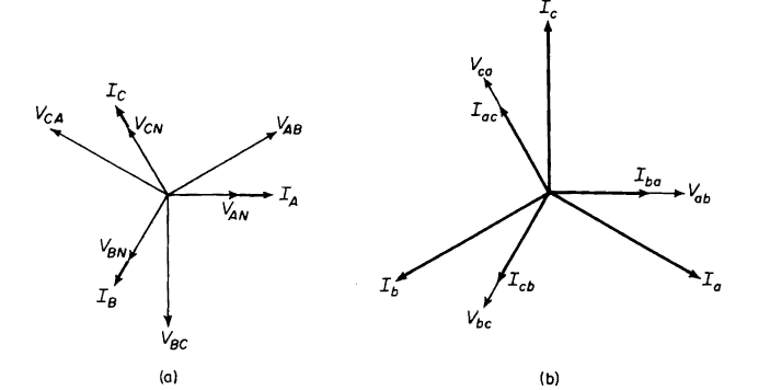
Figure 6-26. Phasor diagram for wye-delta arrangement of Figure 6-25 for ideal transformers supplying balanced noninductive load, (a) Primary wye-connected; (b) secondary delta-connected. |
Figure 6-26 shows the phasor diagram for a wye-delta transformation. From this diagram it is evident that there is a large phase angle between the line-to-line voltages on the wye side and the corresponding line-to-line voltages on the delta side. This angle is 30° with the phases as designated in Fig. 6-26. Angles of 90° and 150° are possible, depending on how the phases on the two sides are designated
Delta-Delta Connection
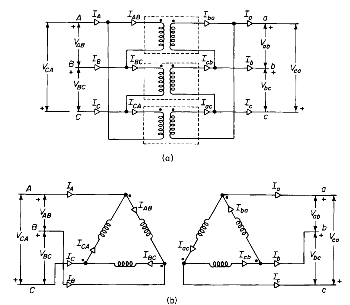
Figure 6-21 shows three single-phase transformers, assumed to be identical, with their primaries connected in delta and their secondaries connected in delta. A common physical arrangement of the three transformers is shown in Fig. 6-21 (a); a schematic diagram typical for 3-phase delta circuits is shown in Fig. 6-21(b).
Figure 6-21. Delta-delta connection, (a) Common physical arrangement of three single-phase transformers; (b) schematic diagram. |
The equivalent circuits of Figs. 6-11, 6-13, and 6-14 apply to each of the three transformers connected delta-delta with or without the ideal transformer. If the three transformers are identical and are operating under balanced 3-phase load and balanced 3-phase voltage conditions, each transformer carries one third of the 3-phase load.
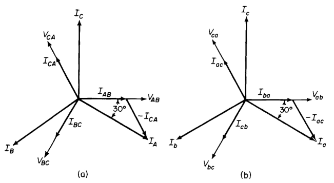
It is evident from Fig. 6-21 that full line-to-line voltage exists across the windings of each transformer. Therefore, the secondary line-to-line voltages Vab, Vbc and Vca are practically in phase with the corresponding primary line-to-line voltages VAB, VBC and VCA. In addition, if the leakage impedance drops are neglected, the voltage ratios equal the turns ratio, i.e.
[6-84] |
Figure 6-22 shows phasor diagrams for a bank of ideal transformers connected delta-delta and supplying a balanced unity power-factor load.
Figure 6-22. Phasor diagrams for delta-delta bank of ideal transformers supplying balanced noninductive load, (a) Primary; (b) secondary. |
In the case of identical transformers, when the third harmonics in the exciting current are neglected, the line currents are times the currents flowing in the windings under balanced conditions. This can be seen by referring to Fig. 6-21 and the phasor diagram of Fig. 6-22(a) as follows
and
from which
[6-85] |
Similarly
[6-86] |
and
[6-87] |
If the exciting current is neglected, then we have
[6-88] |
The delta-delta arrangement is restricted to applications in which neither the primary nor the secondary side requires a 3-phase neutral connection. It is generally used in moderate voltage systems because full line-to-line voltage exists across the windings, and in heavy current systems because the windings need to carry only 1/ or 0.58 of the line current.
AC Power Analysis
Four things come not back: the spoken word; the sped arrow; time post; the neglected opportunity.-Al Halif Omar Ibn
Introduction
The effort in ac circuit analysis so far has been focused mainly on calculating volatage and current. Our major concern in this chapter is power analysis.
Power analysis is of paramount importance. Power is the most important quantity in electric utilities, electronics, and communication system, because such systems involve transmission of power from one point to another. Also, every industrial household electrical device - every fan, motor, lamp, pressing iron, TV, personal computer - has a power rating that indicates how much power the equipment requires; exceeding the power rating can do permanent damage to an appliance. The most common form of electric power is 50- or 60- Hz ac power. The choice of ac cover dc allowed high-voltage power transmission from the power generating plant to the consumer.
We will begin by defining and deriving instantaneous power and average power. We will then introduce other power concepts. As practical applications of these concepts, we will discuss how power is measured and reconsider how electric utility companies charge their customers.
11.1 Instantaneous and Average Power
As mentioned in Chapter 2, the instantaneous power p(t) absorbed by an element is the product of the instantaneous voltage v(t) across the element and the instantaneous current i(t) through it. Assuming the passive convention.
p(t) = v(t)i(t) (11.1)
The instantaneous power (in watts) is the power at any instant of time.
- We can also think of the instantaneous power as the power absorbed by the element at a specific instant of time. Instantaneous quantities are denoted by lowercase letters.
It is the rate at which an element absorbs energy.
The average power (in watts) is the average of the instantaneous power over one period.
Real or average power: P can be defined in two ways: as the real part of the complex power or as the simple average of the instantaneous power. The second definition is more general because with it we can define the instantaneous power for any signal waveform, not just for sinusoids. It is given explicitly in the following expression
The unit for real or average power is watts (W), just as for power in DC circuits. Real power is dissipated as heat in resistances.
11.2 Maximun Average Power Transfer
INTRODUCTION
To obtain the maximum average power transferred from a source to a load, the load impedance should be chosen equal to the conjugate of the Thevenin equivalent impedance representing the reminder of the network.
INTRODUCTION
To obtain the maximum average power transferred from a source to a load, the load impedance should be chosen equal to the conjugate of the Thevenin equivalent impedance representing the reminder of the network.
11.3 Apparent Power and Power Factor
The apparent power (in VA) of the rms values of voltage and current.
Apparent power in S is the product of the rms values of the voltage and the current, S = U*I. The unit of apparent power is VA. The apparent power is the absolute value of the complex power, so it is defined only for sinusoidal excitation.
The Power Factor (cos φ) is the cosine of the phase difference between voltage and current. It is also the cosine of the angle of the load impedance.
The power factor is very important in power systems because it indicates how closely the effective power equals the apparent power. Power factors near one are desirable. The definition:
11.4 Complex Power
Complex power: S
Complex power is the product of the complex effective voltage and the complex effective conjugate current. In our notation here, the conjugate is indicated by an asterisk (*).Complex power can also be computed using the peak values of the complex voltage and current, but then the result must be divided by 2. Note that complex power is applicable only to circuits with sinusoidal excitation because complex effective or peak values exist and are defined only for sinusoidal signals. The unit for complex poweris VA.
Sinusoidal Steady-State Analysis
Three men are my friends --- he that loves me, he that hates me, that is indifferent of me. Who loves me, teaches me tenderness; who hates m, teaches me caution; who is indifferent to me, teaches me self-reliance. -J. E. DingerIntroduction
In this chapter, we want to see how nodal analysis, mesh analysis, Thevenin's theorem, Norton's theorem, superposition, and source transformations are applied in analyzing ac circuits. Since these techniques were already introduced for dc circuits, our major effect here will be to illustrate with examples.
Analyzing ac circuits usually requires three steps.
Steps to Analyze AC circuits:
- Transform the circuits to the phasor or frequency domain
- Solve the problem using circuit techniques (nodal analysis, mesh analysis, superposition, etc. )
- Transform the resulting phasor to the time domain.
Step 1 is not necessary if the problem is specified in the frequency domain. In step 2, analysis is performed in the same manner as dc circuit analysis except that complex numbers are involved. Having done and learned Chapter 9, we are adept at handling step 3.
10.2 Nodal Analysis
Nodal analysis is more commonly used than mesh or loop analysis for analysing
networks. It can be used to determine the unknown node voltages of both planar
and non-planar circuits. Nodal equations are usually formed by applying
Kirchhoff’s Current Law to the nodes with unknown voltages, whereas equations
based on Kirchoff’s Voltage Law are used to form the mesh equations. In order to
apply nodal analysis to a circuit, the first step is to select a reference node or
datum node and then assign a voltage at each of the other nodes with respect to
the reference node. In a circuit with dc sources, the node that has the lowest
voltage is usually selected as the reference node and then the other node voltages
would be positive. Often the node that has the maximum elements connected to
it in a circuit tends to be the reference node. Many electronic circuits have a
metallic chassis and the reference node, usually the negative terminal of the dc
source present in the circuit, happens to be connected to the chassis. It is common
practice to connect the chassis to earth terminal of the utility supply. Then the
reference node is at earth or ground potential and hence the reference terminal is
referred to as the ground terminal, even if it is not earthed. In a power system, the
casing of power appliances is usually earthed and the neutral of the utility supply
remains connected to earth at the source. The reference node in such a power
system is then at zero potential.
In nodal analysis, the voltage at the reference node is assumed to be zero. The
voltages at other nodes are expressed with reference to the datum node. Since the
unknown node voltages are determined by nodal analysis, it is logical to write the
KCL equations at nodes. The procedure can be summarized as follows.
- Select a reference node and treat it to be at zero or ground potential.
- Label the nodes with unknown voltages.
- At each of these nodes, mark currentsin the elements asflowing away from the node.
- Form KCL equations and solve the set of simultaneous equations for theunknown voltages.
The voltage across an element can be expressed as the difference of voltages at
nodes to which it is connected. Use the passive sign convention and mark the
currents to be flowing away from the node at which the KCL is applied. Then the
mutual conductance term would have a negative sign whereas the self-conductance
at a node would be a positive value. This aspect should become clear after a few
examples. It is worth stressing that labelling the nodes and assigning current
direction properly are really important. The practice of this technique would
enable one to write the KCL equations and the matrix equations by inspection.
The basis of nodal analysis is Kirchhoff's current law. Since KCL is valid for phasors, as demonstrated in Section 9.6 we can analyze ac circuits by nodal analysis.
This chapter has shown nodal analysis can be applied to simple circuits and to
circuits with dependent sources. The next chapter describes the sources or signals
used for exciting an electrical circuit and their properties
10. 3 Mesh Analysis
Kirchhoff's voltage law (KVL) forms the basis of mesh analysis. The validity of KVL for ac circuits was shown in Section 9.6 and is illustrated in the following examples. Keep in mind that the very nature of mesh analysis is that it is to be applied to planar circuits.
The two general analytical techniques used in network analysis are mesh or loop
analysis and nodal analysis. This chapter describes mesh analysis, whereas the
next chapter is on nodal analysis.
Mesh analysis is a systematic technique to evaluate all voltages and currents in a
circuit. It is based on Kirchoff’s Voltage Law and Ohm’s Law. This technique can
be applied to ac circuits also. The way to form meshes or loops is described first,
followed by an example. Then a set of simultaneous equations are formed, with the
number of these equations equaling the number of unknown variables to be
determined. These unknown variables are the loop currents or the mesh currents.
The simultaneous equations can be compactly described by matrix equations, and
the solution to matrix equations can be obtained using Cramer's rule. Gaussian
elimination method can also be used to obtain the solution. Solution by hand can
be laborious if the number of unknowns exceeds three. Some examples are
presented, to illustrate the technique of mesh analysis. Since it is essential to be
familiar with passive sign convention, it is explained first.
This chapter has introduced mesh analysis to resistive circuits with dependent and
independent sources. Given a circuit with dependent sources, it is difficult to
specify a particular technique for forming the necessary equations. The number
of independent equations to be formed should equal the number of unknowns. In
that case, the square matrix would have a non-zero determinant and then the
solution is unique. The next chapter describes how nodal analysis can be applied
to such circuits.
10. 4 Superpositon Theorem
Since ac circuits are linear, the superposition theorem applies to ac circuits the same way it applies to dc circuits. The theorem becomes important if the circuit has sources operating at different frequencies. In this case, since the impedances depend on frequencies, we must have different frequency domain circuit for each frequency. The total response must be obtained by adding individual responses in the time domain. It is incorrect to try to add the responses int the phasor or frequency domain.Why? Because the exponential factor e^jwt is implicit in sinusoidal analysis, and that factor would change for every angular frequency w. It would therefore not make sense to add response at different operating at different frequencies, one must add the response due to the individual frequencies in the time domain.
Importance of Superposition Theorem
Network theorems provide insight into the behaviour and properties of electrical
circuits. Superposition theorem is of theoretical importance, because it is
fundamental to linear circuit analysis. A circuit is linear only when it behaves in
accordance with superposition theorem. This theorem states that the linear
responses in a circuit can be obtained as the algebraic sum of responses, due to
each of the independent sources acting alone. Thistheorem defines the behaviour
of a linear circuit. Within the context of linear circuit analysis, this theorem
provides the basis for all other theorems. Given a linear circuit, it is easy to see
how mesh analysis and nodal analysis make use of the principle of superposition.
Properties of Superposition Theorem
There are two guiding properties of superposition theorem. The first is the
property of homogeneity or proportionality, and the second is the property of
additivity.
Limitations of Superposition Theorem
As stated earlier, the linear responses in a circuit can be obtained using this
theorem as the algebraic sum of responses, due to each of the independent sources
acting alone. Current and voltage associated with an element are linear responses.
On the other hand, power in an element is not a linear response. It is a non-linear
function, varying proportionately either with the square of voltage across the
element or with the square of current through the element. Hence it is not possible
to apply superposition theorem directly to determine power associated with an
element. In addition, application of superposition theorem does not normally leadto simplification of analysis. It is not the best technique to determine all currents
and voltages in a circuit, driven by multiple of sources.
Relationship with Mesh and Nodal Analysis
Superposition theorem is valid for linear circuits and analysis of linear circuits is
relatively easy. On the other hand, the principle of superposition is not valid
for non-linear circuits. And the analysis of non-linear circuits is quite complex
complex and difficult. It is possible to apply mesh and nodal analysis to nonlinear circuits. However, within the context of linear circuits, mesh or nodal
analysis of a circuit illustrates how the principle of superposition is ever so
pervasive in defining the behaviour of linear circuits.
The analysis of linear circuits is founded on the superposition theorem. Eventhough the direct use of superposition theorem is not always easy, it remains the
guiding principle for the behaviour of linear circuits. Next we take up Thevenin’s
theorem.
10.5 Thevenin's Theorem
Thevenin’s theorem is a popular theorem, used often for analysis of electronic
circuits. Its theoretical value is due to the insight it offers about the circuit. This
theorem states that a linear circuit containing one or more sources and other linear
elements can be represented by a voltage source and a resistance. Using this
theorem, a model of the circuit can be developed based on its output characteristic.
Let us try to find out what Thevenin’s theorem is by using an investigative
approach.
Thevenin's theorem are applied to ac ciruits in the same way as they are to dc circuits. The only additional effort arises from the need manipulate complex numbers. the frequency domain version of a Thevenin equivalent circuit, where a linear is circuit is replaced by a voltage source in series with an impedance. The Thevenin theorem equivalent circuit must be detemined at eacg frequency. This leads to entirely different equivalent circuits, one for each frequency, not one equivalent circuit with equivalent sources and equivalent impedance.
10.6 Superposition Theorem
The circuits in this set of problems consist of independent sources, resistors and a meter. In
particular, these circuits do not contain dependent sources. Each of these circuits has a seriesparallel structure that makes it possible to simplify the circuit by repeatedly
• Performing source transformations.
• Replacing series or parallel resistors by an equivalent resistor.
• Replacing series voltage sources by an equivalent voltage source.
• Replacing parallel current sources by an equivalent source source.
Each simplification is done in such a way that the voltage or current measured by the meter is not
disturbed. Generally, that requires beginning the simplification at the opposite end of the circuit
from the meter and then working toward the meter.
Eventually, the circuit is small enough to be easily solved using Ohm’s and Kirchhoff’s Laws.
10.7 Summary
- We apply nodal and mesh analysis to ac circuits by applying KCL and KVL to the phasor form of the circuits.
- In solving for the steady state response of a circuit that has independent sources with different frequencies, each independent source must be considered separately. The most natural approach to analyzing such circuits is t The concept of source transformation is also applicable in the frequency domain. o apply the superposition theorem. A separate phasor circuit for each frequency must be solved independently. and corresponding response should be obtained in the time domain. The overall response is the sum of the time domain responses of all the individual phasor circuit.
- The Thevenin equivalent of an ac circuit consists of a voltage source Vth in series with the Thevenin impedance Zth.
- The concept of source transformation is also applicable in the frequency domain.
Subscribe to:
Posts (Atom)